CIRCULAR MOTION AT REGULAR SPEED
The sinusoidal oscillations are represented by a circular motion projection characterised by a regular speed and a circumference diameter.
Figure 13 shows on the left a circle divided into four quadrants, a p point on the centre circumference or rotating counter clockwise. The picture below was made thanks to Geogebra open source software. (http://www.geogebra.org)
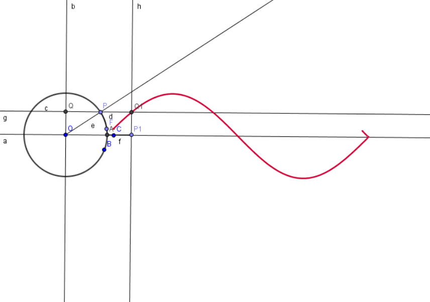
Figure 13
Let’s suppose that the P point on the circumference constantly rotates at a same speed of T period and observe the sinusoidal projection course of P during its motion along the y-axis. The amplitude "A" represents the ray taken along the y-axis.
If during the motion of P we place a panel flowing at constant speed just below the y-axis, by bringing all projections points we obtain a sinusoidal wave chart. Both the circle and the whole period of a sinusoidal wave are divided into 360 degrees. If we now take two points on the circle circumference (R and K) and we track both sinusoids, we can see that they only differ in the starting point. This difference is called phase and it is represented by the Greek letter phi ( φ ) which is pronounced fi (Braille dots1, 2,4).
The phase is shown in degrees and it is measured by joining R and K points with the centre of the circle. The phi difference is said phase difference.
Figure 13 shows on the circumference the two R and K points that produce points P and Q projection. The point P sinusoid is a continuous line uuto touch, while point Q is finely dotted.